Lab 1: Intro to AVR Studio Software.
Welcome to the world of embedded systems. Today you will get an
introduction to the AVR Studio software. We will be implementing
some simple embedded systems to get you used to the tools. To
open AVR Studio on a lab machine, first login and open a terminal.
Type "vmware" to start a windows virtual machine. AVR Studio should
be on the desktop of the virtual machine windows operating system.
YOU MUST shutdown VMWare by going to start->shutdown in the start menu.
Simply pressing the x in the top right corner of the window will not
exit the process, and lock other users from starting a virtual machine
on the desktop.
Objective: Learn how to use
the AVR Development Tool
Getting familiar with AVR Studio
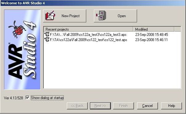
- Open up AVR Studio from the Start Menu
- Create a new project by pressing the (you guessed it) the "New
Project" Button
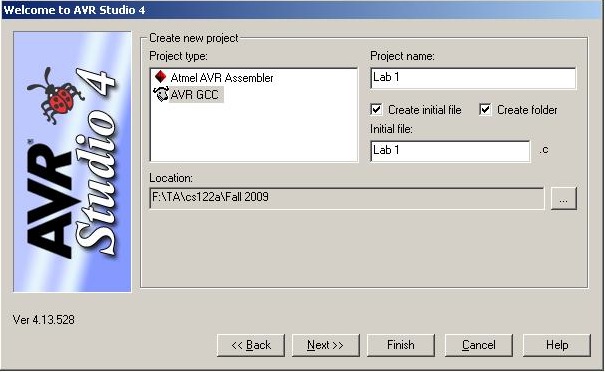
- Call your project whatever you want (We called it Lab 1 here),and
make sure AVR GCC is checked on the left.
- Check the initial file and folders check boxes, and call your
first file "Lab1.c". Click Next
- Select the AVR Simulator as the Debug Platform
- Select the ATmega32 as the Device
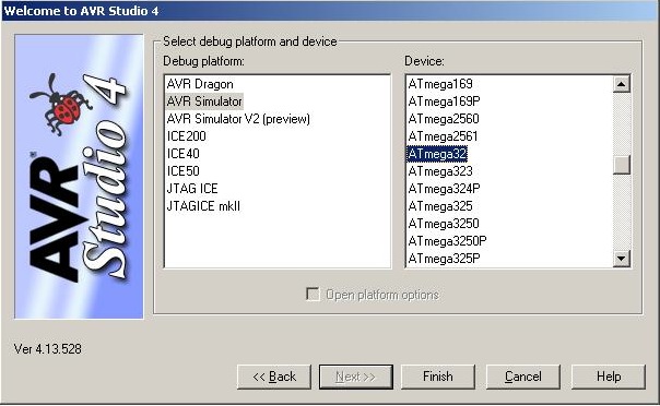
- You are ready to start writing some code for your project. But
first, we want to change some of the compiler options
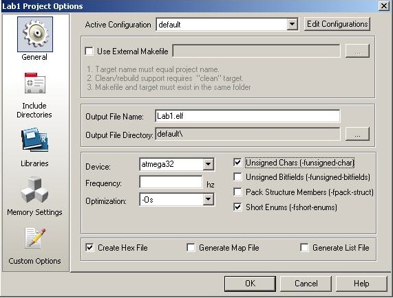
- Select from the Project Menu the menu choice Coniguration
Options. In the General tab, change the optimizations
to -Os (optimize for size). Also click, Unsigned Chars
and Short Enums. The rest of the options can be left unchanged.
These options will drive GCC (the compiler) once we have written
code. Click OK.
- Copy and paste the code below into your Lab1.c file. All this
code does is pass the value of the input on PINC to the output on
PORTA.
- From the Build Menu, select Build. Assuming no errors,
there should be a green light at the bottom saying the application
compiled successfully. You might deliberately breaking the program
to see how AVR Studio handles errors. Since AVR Studio is built
on GCC, the error messages should be familiar to you (unless you
are like me and never have errors in your program).
SAMPLE CODE:
|
#include <avr/io.h>
/*These are macros used to set, clear, or get a single bit from
an 8-bit variable.*/
//For example SET_BIT(temp,3); sets temp = 0x08.
#define SET_BIT(p,i) ((p) |= (1 << (i)))
#define CLR_BIT(p,i) ((p) &= ~(1 << (i)))
#define GET_BIT(p,i) ((p) & (1 << (i)))
int
main(void){
DDRA
=
0xFF;
//Set all pins of port A to output
DDRC
=
0x00;
//Set all pins of pins C to input
while(1)
{
PORTA
=
PINC;
}
return
0;
}
|
- Before running software on an actual chip, we are going to stress
the importance of using the debugger and simulator in this course.
The AVR Studio supplies a state of the art simulator that allows
the designer to monitor pretty much every internal register on the
AVR chips, allowing very quick and easy verification of arbitrarily
complex software.
- The fact that the debuggerand simulator are built into the AVR
Studio IDE makes the simulation process painless. To test the simulator,
select from the Debug menu Start Debugging. The screen
will look like the one below, with all the registers, ports, timers,
etc. on the right, the disassembler window, the watch window, etc.
The standard Step Into (F11), Step Over (F10),
etc. commands are located just below the top menu, and we can see
the program counter off to the left.
- You must first start the debugger by opening the debug menu,
and clicking "Start Debugging". Then click "Run" to begin
program execution. Click" Break" to pause simulation on the
current line of code; you can then use "Step" to execute a single
line of code. Test the pass through application by expanding
the PORTA and PORTC registers off to the right, and then clicking
on some of the bits in the PINC portion of PORTC. You will notice
that once the assignment in the C code happens, the value of the
input will be reflected on the output.
- The debugger will become one of your best friends for some of
the more advanced labs, so learn to use it =).
PART I
You will create a simple application
that sounds an alarm if a garage door is open at night.
- There is a door sensor attached to PINC, pin 0, and a light
sensor attached to PORTC, pin 1. The door sensor is driven high
(a logical value of '1') if the door is open, the light sensor is
driven high if it is day.
- The alarm is connected to PORTA, pin 0. The alarm is sounded
when it is driven high.
- Implement your design using AVR Studio, and use the AVR Debugger/Simulator
to verify the correctness of your design
- Once you are sure your design is working properly, compile
and have a TA verify correctness before continuing.
PART II
You will write a program to check whether
or not an eight bit value is of even or odd parity.
- You might recall that odd parity means that a value has an odd
number of '1's in its binary representation. Even parity is exactly
the opposite.
- The input to your program will be in the entire PortC input.
You will output a '1' to Port A, pin 0 if Port C has odd parity,
and output a '1' to Port A, pin 1 if Port C has even parity.
- Implement your design using AVR Studio, and use the AVR Debugger/Simulator
to verify the correctness of your design
- Once you are sure your design is working properly, compile
it and have a TA verify correctness before continuing.
PART III
You will write a program that simulates
some rudimentary car functions (somewhat contrived and overly simplified,
but you'll get over it)
- The input to the program are:
- Driver Seatbelt On -- (PINC, PIN 0)
- Passenger Seatbelt On -- (PINC, PIN 1)
- Driver Weight -- (PINC, PIN 2)
- Passenger Weight -- (PINC, PIN 3)
- Back Right Weight -- (PINC, PIN 4)
- Back Left Weight -- (PINC, PIN 5)
- Key Ignition -- (PINC, PIN 6)
- Doors Locked -- (PINC, PIN 7)
- The outputs to your application are:
- Seatbelt Beeper -- (PORTA, PIN 0)
- Airbag Enable -- (PORTA, PIN 1)
- Passenger Still in Car Alarm -- (PORTA, PIN 2)
- Your car sensor application will respond to several different
events, including:
- Output a beep if someone is sitting in the driver or passenger
seat if the key is in the ignition and one of the seatbelts
isn't being worn
- Enable an airbag on the passenger seat only if there is
someone sitting there and the seatbelt is connected
- When the car is locked and there is someone still in the
car, sound an alarm
- Implement your design using AVR Studio, and use the AVR Debugger/Simulator
to verify the correctness of your design
- Once you are sure your design is working properly, compile
it and have a TA verify correctness.
POST LAB
INDIVIDUALLY prepare a single-spaced half page report with the following
information.
I. Lab
Objective
II. Personal Contributions
III. Skill learned & knowledge
gained.
Turnin
INDIVIDUALLY prepare and submit all lab files into a tar ball. All .c
files should be included in lab parts, as well as post lab submitted
in pdf and txt format. All files should include a header with name,
login, email, lab section, assignment, and group associates; also include:
"I acknowledge all content is original."
For Example
Name: John Doe
Login: jdoe
Email: jdoe@cs.ucr.edu
Lab Section: 021
Assignment: Lab 1 Part 1
Group: John Doe, Jane Doe, and Joe Doe
I acknowledge all content is original.
Tar ball command: tar -cvzf name.tgz *.c *.pdf *.txt
The tar command will compress all files into a .tgz file with all .c
.pdf, and .txt files in that directory. Do not include unnecessary files!
The .c files be named as follows lab#_part#.c and the postlab#.pdf/postlab#.txt.
For Example:
lab1_part1.c
lab1_part2.c
lab1_part3.c
postlab1.pdf
postlab1.txt
|