|
Joseph Tarango |
|
|
Home
|
|
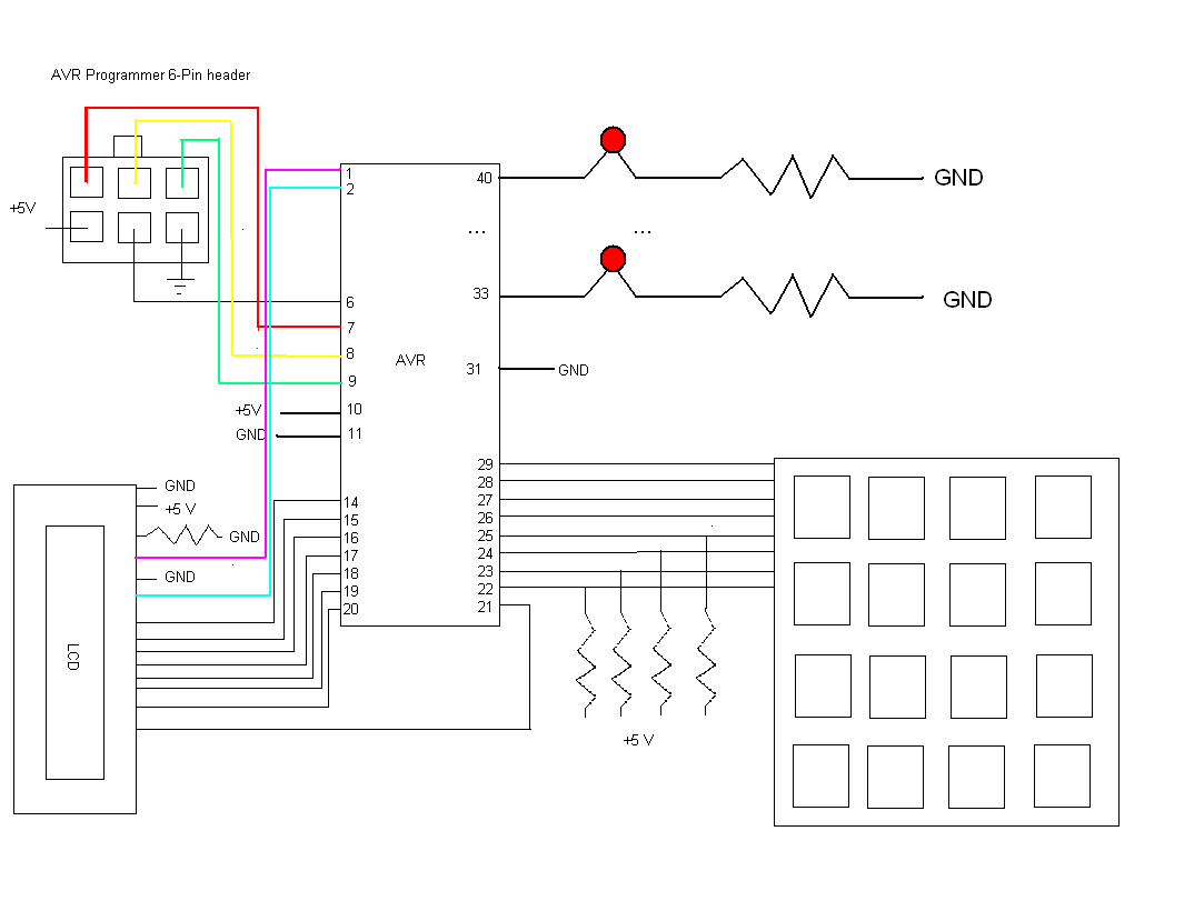
Lab 5: Synchronous State Machines - Reflex Timer GameIn this lab you will be developing a simple reflex timer game. You will be introduced to using the timer on the AVR, as well as implementation of synchronous state machines.Circuit Design:
In this section you are going to learn how the timers work on the ATMega32
microcontroller. The ATMega32 has 3 timers, known as Timer0, Timer1,
and Timer2. Timer0 and Timer2 are 8-bit timers, and Timer1 is
a 16-bit timer. This means that Timers 0 and 2 will count from
0-256 before overflowing, and Timer1 can count from 0-65535. |
|
#include <avr/io.h> #include <avr/interrupt.h>
const unsigned int ONE_MS = 4;
const unsigned int RT_Period = 1000; unsigned int RT_Clk = 0; unsigned int RT_Counter = 0;
enum RT_States { INIT, S0, S1 } RT_State;
//Interrupt service routine //We enter this function ~4 times per millisecond, //we can set a flag that signals a period has passed every period*4 times the function is entered. //If our period is 1000 ms, then we would enter the function 1000*4 = 4000 times before transitioning to next state.
ISR(TIMER0_OVF_vect) { //Timer0 overflow interrupt service routine //Put code in me! //Count up to period and set flag }
void RT_ClkTick() { //Put code in me! //wait until ISR sets flag }
void RT_Tick() { switch(RT_State) { //transitions case INIT: //... } switch(RT_State) { //actions case S0: //... } }
//Configure ATMega32 Timer0 control registers. Correct values can be found in ATMega32 datasheet. void InitTimer() { // Set prescaler to 8. Since the ATMega32 runs at 8Mhz, our timer clock will run at 8MHz/8 = 1MHz. //TCCR0 |= ?
//Enable Overflow Interrupt Enable on Timer0. //TIMSK |= ?
//Initialize starting value of timer TCNT0=0; }
int main() { DDRA = 0xFF;
//Enable Global Interrupts SREG |= (1<<7);
InitTimer();
//init state RT_State = S0;
//init output PORTA = 0x00;
while(1) { RT_Tick(); RT_ClkTick(); } } |
Part 2: Reflex Timer Game
Well done ladies and gentlemen, you've made it this far. Your final task for this lab is to use the timers above to implement a reflex game. The procedure below details how the game should work.1. Output instructions on the LCD screen. The instructions should tell the user that they can start the game by pressing '1' on the keypad.
2. Once the user begins the game, the game should wait for a random amount of time. A good way of generating a psuedo random number is to increment a counter while waiting for the user to start the game.
3. Once the random amount of time has expired, the lights on port A should flash and the LCD screen should direct the user to press '1' again as fast as possible.
4. Once the user has pressed '1' again, the time it took for the user to press the button should be displayed on the LCD screen.
5. If the user does not press the button within 3000 milliseconds, the LCD screen should display a message that the user was too slow. If the user pressed the button before the random amount of time expired, the LCD screen should admonish the user for being a cheater.
6. The game should return to step 1 after the user presses '2'.
In order to implement the game, you may want to set up an additional timer. Remember that the ATMega32 has 3 timers. The first timer can be in charge of transitioning between states, while the second timer keeps track of the time in the game (such as a 3000 ms limit for the user being too slow). Alternatively you could use a single timer with multiple counters - the implementation is up to you.
You must follow the state machine format detailed to you in previous labs and in lecture. You will be graded on how closely you follow the format.
Using the LCD screen
Download the following files and include them in your project. They include necessary functions to interface to the LCD screen. Don't forget to do a #include in your main file to include them in the compilation process.io.h
io.c
You must first call LCD_init() to initialize the LCD screen. Then use LCD_ClearScreen(). You can write to the LCD screen using LCD_DisplayString(unsigned char column, const unsigned char* str) to write the string str to the LCD, starting at column.
POST LAB
INDIVIDUALLY prepare and submit a single-spaced half page report with the following information.I. Lab Objective
II. Personal Contributions
III. Skill learned & knowledge gained.
Turnin
INDIVIDUALLY prepare and submit all lab files into a tar ball. All .c files should be included in lab parts, as well as post lab submitted in pdf and txt format. All files should include a header with name, login, email, lab section, assignment, and group associates; also include: "I acknowledge all content is original."For Example
Name: John Doe
Login: jdoe
Email: jdoe@cs.ucr.edu
Lab Section: 021
Assignment: Lab 5 Part 1
Group: John Doe, Jane Doe, and Joe Doe
I acknowledge all content is original.
Tar ball command: tar -cvzf name.tgz *.c *.pdf *.txt
The tar command will compress all files into a .tgz file with all .c .pdf, and .txt files in that directory. Do not include unnecessary files! The .c files be named as follows lab#_part#.c and the postlab#.pdf/postlab#.txt.
For Example:
lab5_part1.c
lab5_part2.c
postlab5.pdf
postlab5.txt