Lab 5 - Single Cycle Datapath
Intro:
In this lab you will be building a single cycle version of the MIPS datapath. The datapath is composed of many components interconnected. They include an ALU, Registers, Memory, and most importantly the Program Counter(PC). The program counter is the only clocked component within this design, and specifies the memory address of the current instruction. Every cycle the PC will be moved to the next instructions location. The MIPS architecture is BYTE ADDRESSABLE. Remember this when handling the PC, and the memory (which is WORD ADDRESSABLE).
The component connections are outlined in Figure 4.21 of your book. A copy of the image is included below.

NOTE: googleing "VHDL components" may be useful to alleviate signal management.
Deliverables
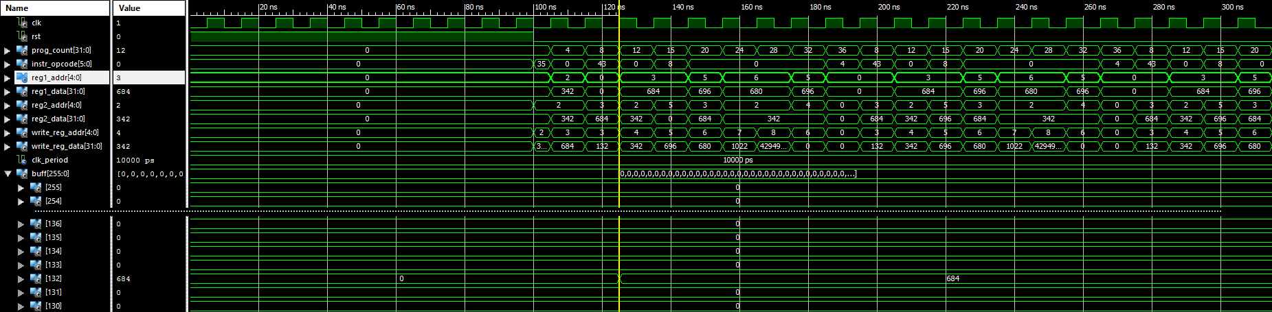
For the turn-in of this lab you should have a working single cycle datapath. The inputs to the top module are only a clk, and reset signal. The datapath should be programed by a .coe file which holds MIPS assembly instructions. The top module should also have output debug signals to monitor the datapath. These signals are given in the top level module's skeleton (cs161_processor.vhd).
For this lab you are not required to build all the datapath components, but you are required to connect them together. The given files, containing most of what you will need, can be found at(cpu component library cpu_components cs161_processor ). If you need more functionality you will have to build the components yourself. To use the given components you only need to include the library at the top of your VHDL file. You do not need to declare a component block. You can directly instantiate them with port/generic maps.
By default the architecture's memory loads data from an init.coe file. The programing occurs when the reset signal is held high. A sample init.coe file is given, but does not fully test the datapath. You will have to extend it.
A more complete sample init2.coe file is given to test the datapath. It is recommended that you extend it with your own tests. For convenience, the assmbly for the init2 file can be found here.
You will have to use your control files from lab 4 to manage the datapath. A tar-ball with the given files can be found here
Functioning CPU/ALU Control Units
- ALU Control Unit
- Control Unit
- *Note: Assumes completed cpu_constant_library
Turn-In:
Each group should turn in one tar file to iLearn. The contents of which should be:
- A README file with the group members names, and any incomplete or incorrect functionality
- All VHDL files used in your Design